In order to provide an accurate guide to electrical connectivity solutions, it is necessary to understand the difference between 12 volt parallel and series circuits. Both circuit types have unique benefits and drawbacks that should be considered when making a decision about which type of circuit to use for a particular application. This blog post will explain the key differences between these two types of circuits so that you can make an informed decision about which one is right for your needs.
Define what a circuit is and its purpose
A circuit is a continuous, closed loop composed of electrical or electronic components through which electricity can flow. The purpose of a circuit is to regulate the power supply and pass an electrical current from the source to either power or activate an appliance or device. Circuits comprise elements such as resistors, capacitors, transistors, integrated circuits, switches and wires that can be connected to form larger networks for controlling complex systems and devices. An uninterrupted path allows for electrons to move freely so that they can be used as energy. This expansive network of circuits creates a way for electricity to be directed with precision in order to meet specific requirements.
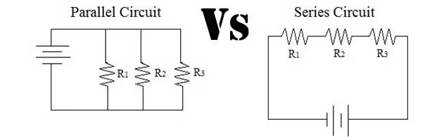
Two types of circuits – parallel and series
Electrical circuits come in two varieties – parallel circuits and series circuits. Parallel circuits offer the advantage of having each electrical device receive the same amount of power, as each device is connected in such a way that they take up an equal segment of the circuit’s path. On the other hand, series circuits are designed to be more efficient as they connect one component after another so that there is no wasted energy. This can be particularly beneficial when multiple devices need to share a common power source. While these two forms of circuits have their advantages and disadvantages, both remain necessary for achieving desired outcomes related to electricity and power distribution.
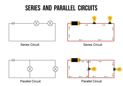
How a parallel circuit works,
A parallel circuit is an electrical network that contains several paths for current to move, as opposed to a series circuit in which charge follows a single path. When two or more components are connected in parallel in a circuit, the voltage applied to each component is equal while the total current is determined by the combined resistance of all the components. In case one of the branches is removed from the circuit, current will still flow through the other paths and reach its destination. This property makes parallel circuits advantageous when supplying power to different devices as they can be connected independently of other devices, even if one gives up then power supply won’t stop obliging. Furthermore, it allows us to increase our total output current by adding extra branches in parallel with existing branches.
How a series circuit works
A series circuit is an electrical circuit where components are arranged in a line, one after the other. In this type of circuit, there is only one path for current to flow. This path starts from the positive terminal of the battery, passes through each component connected in series, and ends at the negative terminal of the battery. As current flows through the components, it loses energy due to resistance. This means that with each component connected in series, there is greater load on the source and less energy available downstream. As a result, the voltage delivered by each component is lower than that supplied by the source. It is important to note that if any component in a series circuit fails, then no electricity will flow beyond it because there will be a break in continuity of the single path.
Compare and contrast the two types of circuits in terms of voltage and current
Parallel and series circuits differ in terms of voltage and current. Parallel circuits are characterized by a uniform voltage across all components, but the total amount of current is determined by the components in it. In contrast, the total amount of voltage shared in a series circuit remains the same but the individual components may vary in current across them. This makes parallel circuits ideal for more complex electric systems, where multiple components receive power simultaneously based on their own draw rather than that of other attached circuitry. Meanwhile, series circuits are suitable for simpler applications as they allow electricians to connect components without having to track individual resistances or supply levels.
Conclusion: Paths of current flow
In conclusion, circuits are electrical networks consisting of multiple paths for current to flow. There are two types of circuits – parallel and series. In a parallel circuit, there is more than one path for current to flow, while in a series circuit, there is only one path for current to flow. Parallel circuits have higher voltage but lower currents, while series circuits have lower voltage but higher currents. Thanks for reading!
FAQs about Parallel vs Series circuit
There are two types of circuits – parallel and series. In a parallel circuit, there is more than one path for current to flow, while in a series circuit, there is only one path for current to flow. Parallel circuits have higher voltage but lower currents, while series circuits have lower voltage but higher currents.
If you want to wire a 12 volt parallel circuit, you will need to attach the positive terminal of each battery to the positive terminal of each device, and the negative terminals of all the batteries together. Then, do the same for the negative terminals. Make sure that all devices are connected in parallel with each other.
If you want to wire a 12 volt series circuit, you will need to attach the positive terminal of each battery to the positive terminal of each device, and the negative terminals of all the batteries together. Then, do the same for the negative terminals. Make sure that all devices are connected in series with each other.
Parallel circuits are circuits in which there is more than one path for current to flow. This means that if one path is blocked, the current can still flow through other paths. This makes parallel circuits ideal for more complex electric systems, where multiple components receive power simultaneously based on their own draw rather than that of other attached circuitry.